LED diodes – how to flash and light
Recently there was silence on Starter Kit, because before holidays I was preparing to Bootstrap 9.4, what took most of my free time. Now, taking advantage of free day I’m making up for it.
Previously, we were dealing with reading from external sensor (photoresistor). Now we will try to show this reading.
We will use 7 LED diodes arranged in a line making a kind of indicator – the more light falls on the photoresistor, the more diodes will light. Beginning from the end – how it looks in action:
Arduino’s Eye from Starter Kit on Vimeo.
Forgive poor quality, but mobile phone camera is the only tool I can use to perpetuate my experiments with Arduino.
But despite of that the effect is visible. Behind the frame I zoom in and out the photoresistor to a lamp as the diodes are lighting up and fading out.
LED diodes are mounted directly to the breadboard with cleverly bended and cut terminals so they are arranged in a line and sitting firmly in the board.
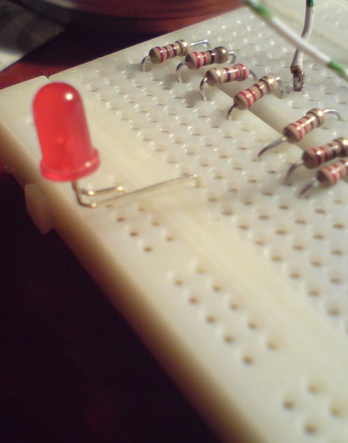
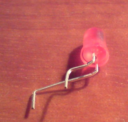
The photo is slightly unsharp (again because of the mobile phone) but you can see in which way the diode is placed. In one of the lower rows of holes the ground is connected and this connection is shared by all diodes. The next photo shows exactly, how the terminals are bended.
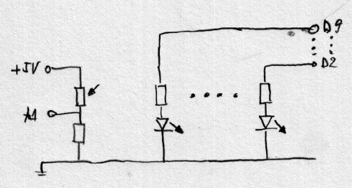
The ground from Arduino (GND) becomes connected to the lower row on breadboard. Voltage divider with photoresistor is placed between ground and supply from Arduino. As the second resistor a 5.6 kΩ is used.
Taking into account that the resistance of my photoresistor varies from hundreds Ω to a few MΩ, voltage drop on 5.6 kΩ resistor would vary from almost 5V to just over 0V, thus the readings from analog input would be in full scale from 0 to 1023.
All the diodes are connected to the ground rail. Every diode is wired to digital output through a resistor. The resistor’s role is to limit current flowing through the diode. It’s not about safety of the diode, it’s about safety of Arduino digital output.
CODE:
// pin 1 isn't used
// when the value is 0 - it shouldn't light
int leds[] = {-1,7,8,2,3,4,5,6};
int photoPin = 0;
int size = 8;
int val = 0;

void setup()
{
  //setting
  for (int i=1; i< size; i++) {
    pinMode(leds[i], OUTPUT);
  }
}

void loop()
{
  val = analogRead(photoPin);
  val = val/128;
  for (int i=1;i<size;i++) {
    if (i <= val ) {
      digitalWrite(leds[i], HIGH);
    } else {
      digitalWrite(leds[i], LOW);
    }
  }
  delay(200);
}
leds is array containing digital outputs numbers to which the diodes are connected in sequence. Because the array is numbered starting from 0, entering non-existent output value and using the table index always from 1 cause turning off all the diodes when the light intensity is lowest.
Our display has 8 states (from 1 to 7 and ma 8 zero state with all diodes out), so we divide the reading from analog input by 128, what gives result from 0 to 7, which describes number of diodes to be lighted.
Summary
It’s first of the articles about LED diodes. One of the following will be about controlling LEDs in number higher than 14. In this case controlling one diode with one digital output, what was presented above, is no more effective.
HI,
nice job. This helped me a lot with my project.
I want to make a LED light board to my dog house and combine it with solar cell. I found a web with many kind of LEDs here: http://www.electron.com/leds
Can you recommend me the most suitable LED size for my application?
Board size should be: 30″ x 5″ mounted under the roof.
Thank you,
Peter
Nice to know it was helpful.
Regarding Your question – hard to say. Smaller LEDs allow to make ‘higher’ resolution of display, but require more LEDs which is harder to control. You can take a look at LoL shield http://www.youtube.com/watch?v=ctSmMJP3fcg it uses LED with 3mm diameter (LoL shield is a bit larger than Arduino itself but not much).
With size 30″ x 5″ I would go rather with 5 mm LEDs. But even if You will use 5mm LED and 5 mm of space between LED You still need 1500 LEDs for such sign. Will require a bit of LED drivers (TLC5940NT gives You 16 channels so You would need almost 100 such drives. Each in PDIP28 – well, quite a lot of PCB space needed :)