Arduino SMS and not only
GSM module for Arduino lets you convert it into a cell phone :) Well, somewhere about a cell phone.
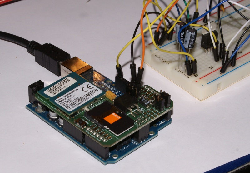
Let’s start from the beginning. First, we need the the module and a valid SIM card. The first issue – power. The GSM module is quite demanding in this regard. Not every USB port provides enough power to feed an Arduino with GSM module. As a result, the communication breaks up immediately afer entering PIN code. In this case you will need an additional power supply. How to – more on that later.
Testing the module
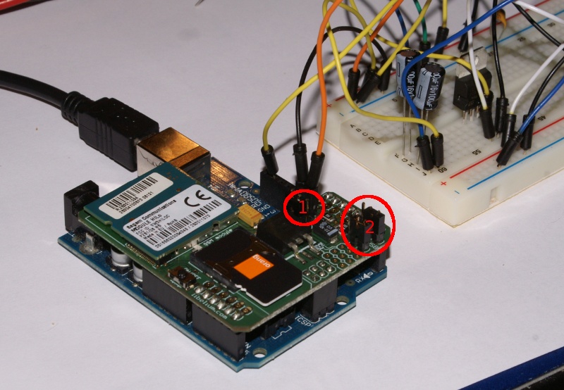
GSM module can work in two serial comunication modes. It “talks” with Arduino or a computer connected to Arduino’s USB port. The first is used during normal operating, the second can be used for testing. To choose the second mode you should follow these steps:
- remove the ATMega from Arduino (Arduino will be used only as power supply, we will be utilizing also the USB/Serial converter)
- set operating mode jumpers to USB gateway
- insert SIM card
- connect Arduino to computer
- press ON/OFF button on module and hold it for two seconds
- start the terminal software (gtkterm), choose serial port (parameters: 115200 8,N,1, line ending – CR (not CR+LF)) and write AT commands in UPPERCASE
- AT – the answer expected is “OK” – this means the connection has been estabilished
- AT+CPIN=”ABCD” – where ABCD is the PIN code of SIM card inserted – we should get “OK” if it’s correct or “+CME ERROR 16” if not
- the module starts to search for GSM network – if it will be returning “OK” for “AT” command in the next few seconds, means the USB port succeeded to power the device. In case of a failure, begin to prepare additional power supply
- if it’s working we can try some commands:
- AT+COPS? – returns the name of GSM provider
- AT+CPBR=# – returns an entry from address book (# is a number)
- AT*PSCPOF – turns the module off
- ATD##########; – call the number # (of course, a conversation is impossible, for now)
- ATH – ends the call
- sending a SMS – follow these steps:
- AT+CSCA? – download the SMS center number
- AT+CMGF=1 – SMS sending mode – 1 is tezt
- AT+CMGS=”#######” – target number
- after AT+CMGS begin to enter the message content in a single line and end with character 0x1A (hex code)
- wait for the SMS ;)
Full AT command list for Sagem HiLO modem is here.
GSM module has a microphone input and speaker output, so it’s able to act as regular cell phone :)
Power feeding
There is a jumper specifying power source. When set in “5V” position, Arduino is used for powering the module. By choosing “ext” we are able to power it from external power supply. The manufacturer reccomends a 12V, 2A supply. When using a supply with current efficiency lower than 2A, a 220 μF capacitor should be added. I tested whole device feeding Arduino from USB port and GSM module from 12/0.5A power supply with 200 μF capacitor and 5V voltage regulator (L7805).
Controlling it from Arduino
When serial mode communication jumper is set to Arduino, the module can be connected to Arduino serial port and controlled by commands sent from Arduino (using Serial.println). An example code:
int led = 13;
int onModulePin = 2;        // the pin to switch on the module (without press on button)
int timesToSend = 1;        // Numbers of SMS to send
int count = 0;

void switchModule(){

  digitalWrite(onModulePin,HIGH);
  delay(2000);
  digitalWrite(onModulePin,LOW);

}

void setup(){

  pinMode(led, OUTPUT);
  pinMode(onModulePin, OUTPUT);
  Serial.begin(115200);               // the GPRS baud rate
  switchModule();                    // swith the module ON

  for (int i=0;i<5;i++){
    delay(5000);
  }
   Serial.println("AT+CMGF=1");         // set the SMS mode to text
}

void loop(){

  while (count < timesToSend){
    delay(1500);

    Serial.print("AT+CMGS=");               // send the SMS the number
    Serial.print(34,BYTE);                  // send the " char
    Serial.print("*********");              // send the number change ********* by the actual number
    Serial.println(34,BYTE);                // send the " char
    delay(1500);
    Serial.print("Arduino SMS...");     // the SMS body
    delay(500);
    Serial.println(0x1A,BYTE);                // end of message command 1A (hex)
    delay(5000);
    count++;
  }

  if (count == timesToSend){
    Serial.println("AT*PSCPOF");             // switch the module off
    count++;
  }

}
Finally – as you can see, this module has a weird shape. Well, it fits perfectly to another shield – GPS :)
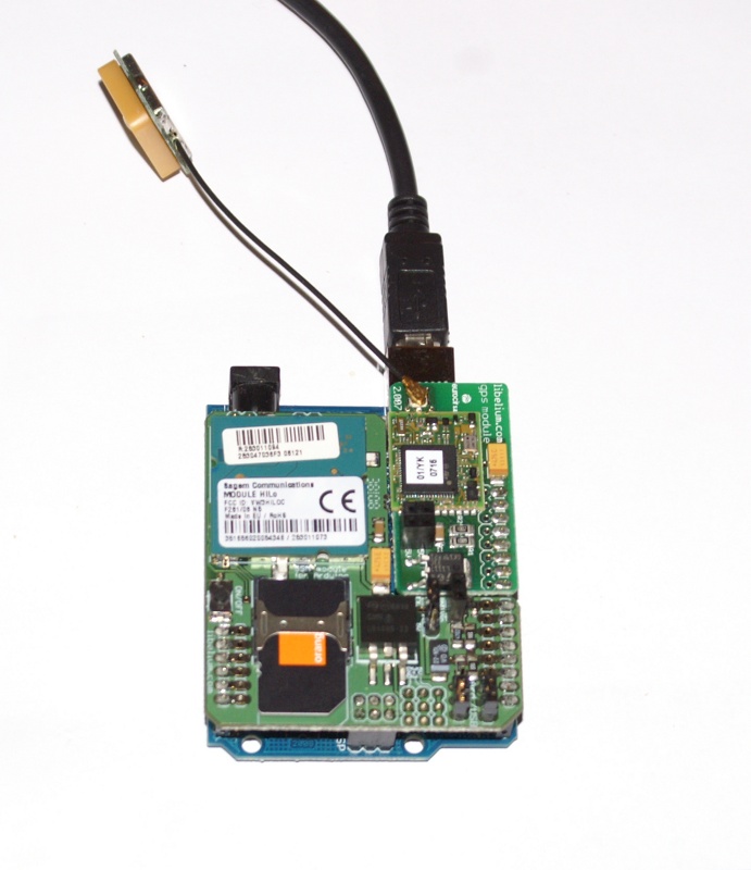
But about it later.
Hi
I am interfacing Arduino pro mini with MC37i gsm module. Can you tel me how to I switch the Gsm module on using Arduino.
Also tell me where does the cts,dtr,rts etc connections in MC37i go in arduino.
Kindly help me out.