Arduino and time, or DS1307
Arduino hasn’t internal clock. It means some operations connected with time (delaying for specified interval) are possible, but date and time controlling isn’t so easy.
To let Arduino know, what time is it exactly, there is external clock device needed. Such a device is Dallas DS1307, available on Nettigo.eu in form of Arduino-connectable module. This module has a battery back-up, so once set, the time isn’t deleted after shutting Arduino down.
Assembly
The module is already soldered, but connecting to Arduino remains open issue. It looks like the following:
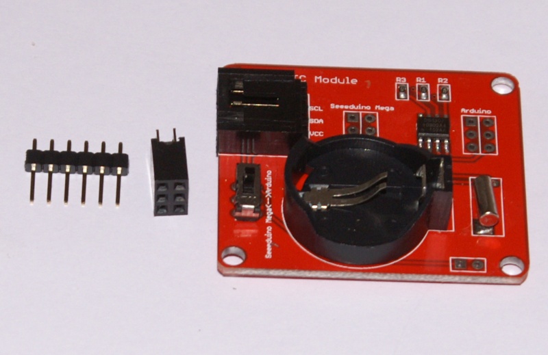
In the left upper corner there is 4-pin header socket with 2.54 mm raster. Unfortunately we still haven’t cables for this socket in stock. You have to scare it up or connect through ICSP socket using goldpins. Those elements are provided with the module, but need soldering (simple even for beginners).
Using the cable we can connect the module to any controler supporting I2C protocol.
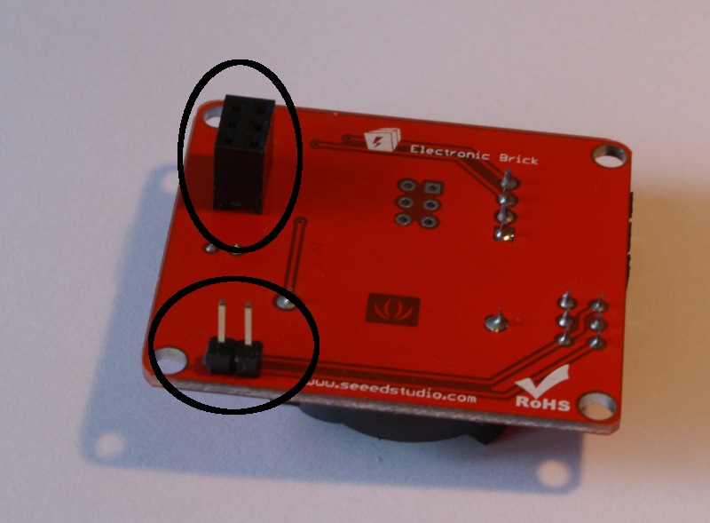
ICSP socket (from which the module is powered) has two positions to which it could be soldered. The first is for Arduino Duemilanove and its clones (taking pinout and size into account) or Seeeduino Mega. With such a connection the module is incompatible with Arduino Mega (relative position of ICSp pins and I2C bus output is different).
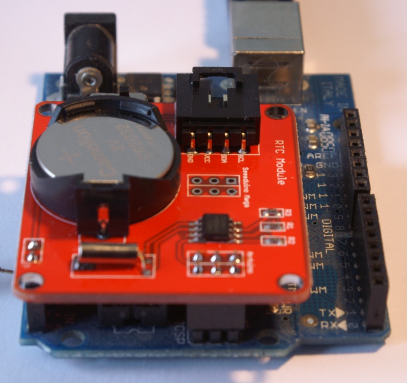
Of course, it always remains to solder wires instead of goldpins and ICSP and then we are able to connect with every microcontroler supporting I2C. How the module with soldered socket and goldpins looks show the pictures below:
What can we do?
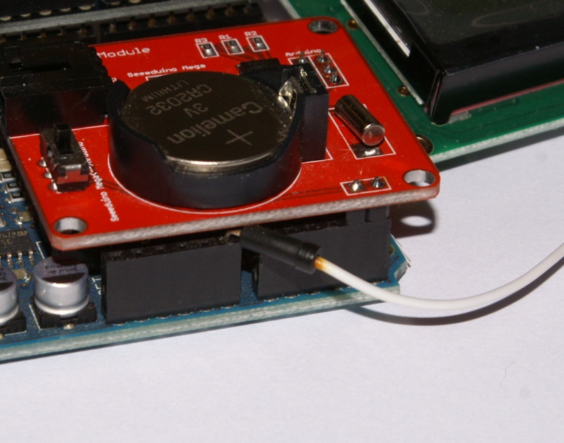
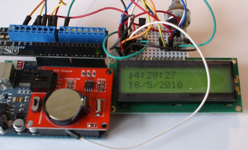
We are going to build simple clock displaying date and time on LCD. Wiring of the LCD is the same as in LCD description. We connect the LCD, mount soldered clock module and it looks much about like this:

What’s in the picture? Apart from LCD Kit you will see a half of ScrewShield – a solution for falling out wires. Thanks to it the junction is solid and nothing falls out, even when pulled.
Clock module is mounted so it shuts Analog and power connectors off, what makes the connection more difficult on first sight. In fact, after mounting the module, there is rather no possibility to connect anything to the analog inputs. However, if we bend a wire using small pliers, we will be able to reach it before mounting the module. What is more, the module will press the wires, preventing them from falling out. This is how the power is provided to LCD:

It only remains to write the code. This is sketch handling everything:
#include <LiquidCrystal.h>
#include
#include <Wire.h>
#include
#include

//Set the clock in setup or not?
boolean SETUP=false;

LiquidCrystal lcd (12,11,10,9,8,7);

void setup()
{
  Serial.begin(9600);
  lcd.begin(16,2);
  if (SETUP) {
    RTC.stop();

  RTC.set(DS1307_SEC,1);        //set the seconds
  RTC.set(DS1307_MIN,49);     //set the minutes
  RTC.set(DS1307_HR,19);       //set the hours
  RTC.set(DS1307_DOW,6);       //set the day of the week
  RTC.set(DS1307_DATE,1);       //set the date
  RTC.set(DS1307_MTH,5);        //set the month
  RTC.set(DS1307_YR,10);         //set the year
  RTC.start();
  }

}

char time [20];
char date [20];

void getTime(char *t, char *d) {
  sprintf(t,"%.2i:%.2i:%.2i",
   RTC.get(DS1307_HR, true),
   RTC.get(DS1307_MIN, false),
   RTC.get(DS1307_SEC, false)
   );
  sprintf(d, "%i/%i/%i",
   RTC.get(DS1307_DATE, false),
   RTC.get(DS1307_MTH, false),
   RTC.get(DS1307_YR, false)
 );
}
void loop()
{

  getTime(time, date);
  Serial.println(time);
  lcd.setCursor(0,0);
  lcd.print(time);
  lcd.setCursor(0,1);
  lcd.print(date);
  delay(1000);

}
The library handling the module is for download from the product page, Related Files section.
The library supplied with the module will do for communication with DS1307 through I2C. I2C bus in Arduino gets out through analog pins 4 and 5. Exerting them for reading analog values won’t be possible.
In the sketch there is SETUP variable defined, set to true, what will in advance set the clock to a cetain time. That’s done to simplify this sketch.
So, in the code, in setup we are setting a time from near future, switching SETUP to true and loading the sketch. Arduino will switch the clock, but don’t worry as yet the time is from the future. We are waiting until the stored time comes and in this moment resetting Arduino or loading sketch again. setup function will set the time once more, but now it will be good.
After that, the sketch needs to be loaded again, but this time with SETUP set to false. From no on, restarting Arduino won’t reset the clock.
For the sake of clarification, setting the clock is done like this – stopping the clock by RTC.stop(), next setting all the segments by RTC.set() using constants pre-definied for setting seconds, minutes, hours, days, months, years and weekdays. After that, the clock is released by RTC.start(). If the module has a battery installed, the time will be measured continously and after next start using of RTC.start() won’t be needed.
We have the time set, now it remains to read and display it. For reading there is RTC.get(SEGMENT,reading_from_buffer) function available. SEGMENT is a pre-defined constant, the same as used in RTC.set to set every part of time (minutes, seconds and so on). reading_from_buffer value is a logic (boolean) variable and if it’s true, then the library will ask for time and store its reading in buffer. This will allow next RTC.get with reading_from_buffer set to false to read the same time (it’s possible that next readings will be done after the time changes, eg. from 23:59:59 to 00:00:00).
In the sketch above time is readed in function getTime taking two arguments – character buffers, in which date and time will be stored, formatted with sprintf function. It only remains to display read values on two lines of the LCD. This is done in loop.
Sketch for download here.
How it works:
Can you provide code for RTC.gettime functions
@Yogesh
You mean RTC.get and RTC.set ? These are parts of library provided with this module. You can download it from http://www.nettigo.eu/pub/files/docs/1287435529_DS1307.rar