Hall effect sensor
Hall effect sensor is a sensor utilizing the Hall effect to measure magnetic field. Briefly speaking, it’s about diference in voltage charges within a conductor placed in magnetic field.
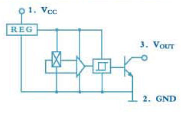
CS3144E available in Nettigo store is a Hall effect sensor in TO-92UA package. It consists of voltage regulator, Hall voltage generator, differential amplifier and Schmitt trigger. The output is open-colector type.
Internal sensor’s structure:
And it looks like the following:
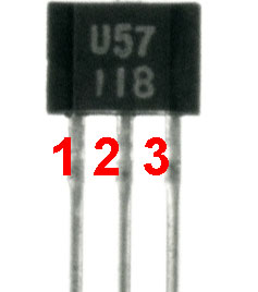
Don’t bother about the markings – it’s totally different device, but the package is the same. I’m just not able to make a decent photo in macroscale ;) Of course, the terminal no. 1 is the first from the left, when looking at the package from the marked side.
The sensor gives two voltage values on its output: VOH, near to the supply voltage and VOL, near to zero. High value appears on the output when it’s no magnetic field. To be more accurate, when the field around our sensor is to weak to exceed the threshold value. When the field strength will increase enough, the output voltage will fall hardly to zero. It will return to the previos state only when the field strength will become lower, and the threshold value for
L->H change is lower than for H->L. To illustrate this – a graph:

Such a output voltage levels are so called hysteresis. And why there’s no single threshold value? In this case, when the field strength is near threshold
value, output voltage switches rapidly between high and low states.
With two threshold values, there is no problem – when magnetic field reaches BOP value, output switches from high to low state. It changes in the opposite direction only when the field reaches BHP value, which is lower than BOP.
Thanks to this, there is no blinking effect, which would appear when the switching is performed independently from the direction.
Simplest aplication
Of course, the Hall effect sensor has many sophiscated applications, for example in a rpm meter, but I’ll show the simplest one – turning a LED diode on and off with a magnet.
The sensor gives two voltage levels on its output, so the best solution is to wire it up to one of Arduino’s digital pins. To do this we must, as usual, declare the pin as input in setup() function entering:
pinMode(hallPin, INPUT)
where hallPin means the digital pin number – I chose 8. Another thing to do is to pull it up using internal resistor. In other case, the input will remain unconnected and receive interferences, which will result with the diode blinking in a random way. So, immediately after the previous line, we are adding:
digitalWrite(hallPin, HIGH);
As a output we choose another digital pin. The best is 13th, because most Arduino models have internal LED diode connected there. The rest of the code rather doesn’t need any comments – the input is read in a loop and the output is set according to its value. The whole program code is here:
const int hallPin = 8;
const int ledPin = 13;

int hallState = 0;

void setup(){
  pinMode(hallPin, INPUT);
  pinMode(ledPin, OUTPUT);
  digitalWrite(hallPin, HIGH);
}

void loop(){
  hallState = digitalRead(hallPin);

  if (hallState == HIGH){
    digitalWrite(ledPin, LOW);
  }
  else{
    digitalWrite(ledPin, HIGH);
  }
}
Connection diagram (just in case – there’s rather no vaguenesses):

External LED diode is optional, unless our Arduino has a built-in one. In the other case it should be connected, as shown. A resistor limiting the current can be safely omitted.
This is how an assembled circuit looks:

And it works in this way.
As you can see, I tried two different magnets and the difference in range is clearly visible. Unfortunately, I hadn’t any neodymium magnet, but I suppose the sensor would react from farther distance.