Humidity sensor
Every amateur and professional meteo station requires humidity sensor to be completely happy. This sensor along with a termometer allows to forecast so called “dew point”. Dew point is a temperature at which (and at a certain humidity) vapor water condenses into water. Usually it produces dew on grass, but in specific conditions also allows to calculate cloud base or figure out why in the kitchen plaster falls out from the ceiling ;-).
Capacitor
HCH-1000 available in Nettigo is a capacitive humidity sensor. Capacitive means that the sensor is a capacitor, which capacitance proportionally depends on the humidity. Average value is about 330 pF.
Capacitor is, in a simple explanation, an element which stores electric charge, or even simpler (electronics engineers – please forgive me) – some kind of very low capacity accumulator.
Calculating the capacitance
Everyone, who had anything to do with an accumulator (even in a mobile phone) know that charging and discharging it takes certain amount of time. This amount depends on capacitance of the accumulator and its electric demand. The same rule concerns capacitors.
Professionally, it’s called RC circuit (because it consists of a resistor and a capacitor connected serially).
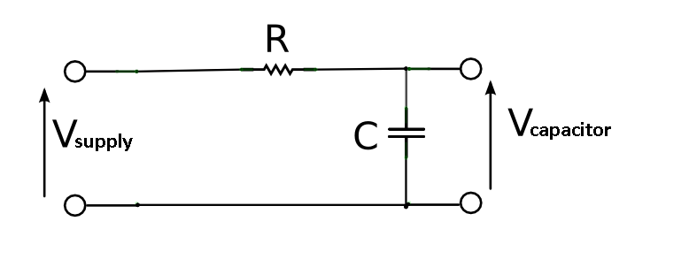

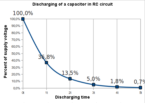
This graph shows the time, in which the voltage drop on the capacitor achieves a percent of supply voltage (V supply). It shows that 63,2% of the voltage will be achieved in one time unit, which can be calculated from the following equation:
t = RC
where:
- t – time in seconds
- R – resistance of the resistor in Ω
- C – capacitance of the capacitor in farads
Assuming the resistor is 10 MΩ and average capacitance of the sensor is 330 pF, charging to 63,2% of supply voltage will take:
t = RC = 10 MΩ * 330 pF = 10000000 Ω * 0,00000000033 F = 0,0033 s
It’s easier to calculate using units prefixes
t = 10 * 10^6 Ω * 330 * 10^-12 F = 10 * 330 * 10^-6 = 3300 * 10^-6 = 3300 µs.
Charging to higher parts of the supply voltage is, according to the chart, multiplication of this time. For example, for 95% it takes 3 times longer.
t = 3RC = 3 * 3300 * 10^-6 = 9900 µs
Discharging is reversed process in which correlation between the time and voltage value is like the following:
Implementation in Arduino
The basic model of this circuit should perform the following steps:
- Charging the capacitor
- Checking charge level
- Measuring charging time
- Discharging the capacitor
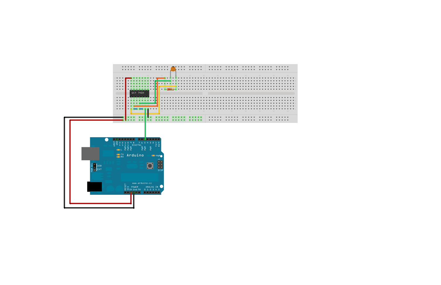
The following picture shows a connection diagram of the basic model.

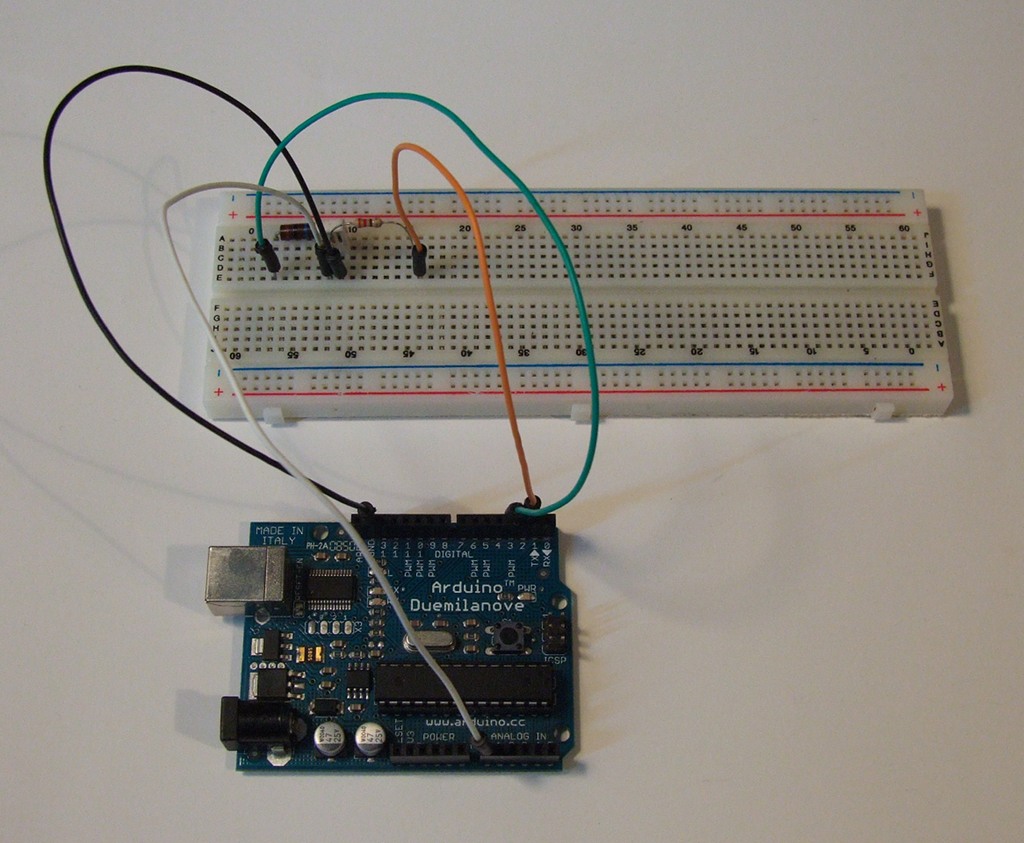
Pin 3 is responsible for charging the capacitor, pin 2 for discharging. Analog pin 0 measures voltage drop across the capacitor. To pin 3 is attached to a chrging resistor 10 MΩ, To PIN 2 – discharging resistor 220 Ω.
Capacitance measurement procedure is composed of two consecutive subprograms.
Discharging:
In this subprogram pin 3 is set as “INPUT” and in “LOW” state; pin 2 is set as “OUTPUT” and also in “LOW” state.
This makes the current to flow from the capacitor to the discharging resistor. Discharging level is monitored by analog pin 0. By reaching 0V, the program ends.
void discharge()
{
  // Setting pins in discharging mode
  pinMode(CHARGE_PIN, INPUT);
  digitalWrite(CHARGE_PIN, LOW);
  pinMode(DISCHARGE_PIN, OUTPUT);
  digitalWrite(DISCHARGE_PIN, LOW);
  // Waiting for the capacitor to reach 0V
  while (analogRead(VOLTAGE_CHECK_PIN) > 0);
}
Charging:
Charging subprogram sets pin 3 in “OUTPUT” mode and in “HIGH” state; pin 2 in “INPUT” mode. Analog input pin 0 is monitoring charging level. Simultaneously, the time of charging is counted by “micros” function. This makes the current to flow from pin 3 through charging resistor to the capacitor.
“Analog Inputs” are analog/digital converters (they convert analog voltages to binary values). These converters have 10-bit resolution. It means they can give out one of 1024 (2^10) values, where 0 is 0V and 1023 means 5V. Because 5V is supply voltage of our RC circuit, we can assume that 63,2% of this voltage is the following value:
1023 * 0.632 = 646,535
After rounding – 647.
unsigned long charge()
{
  // Setting pins in charging mode
  pinMode(DISCHARGE_PIN, INPUT);
  unsigned long begin_time = micros(); // Loading the initial time
  pinMode(CHARGE_PIN, OUTPUT);
  digitalWrite(CHARGE_PIN, HIGH);
  // Waiting for the capacitor to reach 63,2% of supply voltage
  while (analogRead(VOLTAGE_CHECK_PIN) < 647);
  unsigned long end_time = micros(); // Loading the final time
  return end_time - begin_time; // Calculating the charging time
}
This function returns the capacitor charging time (to 63,2%). The time is counted in microseconds.
Of course it’s possible to increase the charging level. It will cause increased accuracy and decreased frequency of measurements.
Interferences
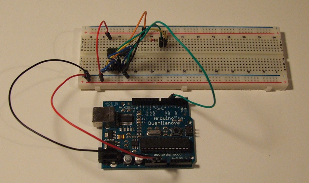
If you have assembled the circuit properly, run the first example.
It returns the capacitor charging time through “Serial Monitor”. Interestingly, instead of planned 3300 µs there is about 4300. If returned values are more random, try to touch something metal and well grounded (e.g. a radiator). Perhaps source of these interferences are you.
Why so high value? Because the program itself (with delays in individual operations), and electrical circuit are entering it. It also has capacitance, so is a capacitor. Even a pair of parallel wires has capacitance. To check, how the circuit capacitance affects the result, remove the sensor from the board and run again. This time the result equals 684 µs, the capacitance of the circuit itself probably equals:
t = RC
C = t/R = 684 * 10^-6 s / 10 * 10^6 = 68,4 * 10^-12 = 68,4 pF
To check the impact of Arduino signal wires on the circuit, you can experimentally make them stick together or separate from each other and check in which way it changes the final value. For me, with the wires sticking together it increases to more than 1000 µs.
I would therefore draw attention to the accuracy, quality and stability of operation of the circuit.
We can assume that the capacitance of the circuit is parallelly joined with our sensor. Because total capacitance of two capacitances joined parallelly equals their sum, we can substract this sum from the result returned by the program, which will give approximate capacitance of the sensor in a certain moment.
Callibration
Of course, nothing in the world can not accept that the program returns accurate value. There always must be reference points. This exactly is callibration. It’s all about putting the sensor in a certain environment, whose parameters are known. For better explanation, I’ll use temperature sensor as example.
If we connect the temperature sensor to analog input, we can’t assume that certain voltage described by the manufacturer denotes a certain temperature. There always are unwanted resistances and parasitic capacitances, falsifying the measurement.
Because of that we must manually calibrate the sensor, which means to create a surrounding, whose temperature is known to us. As we remember from physics, the water has two states in which we know the temperature hardly in 100%. The first is ice with 0 °C, the second – boiling water – 100 °C.
After covering the sensor, in order to protect the terminals from water, we are putting it alternately in this two environments and writing down values returned by “analogRead”. These are our reference points.
Assuming every sensor is linear (what means temperature increase is directly proportional to increase of voltage emitted to Arduino) and you have some skills in math, you probably know the linear function equation is y = ax + b. It will be the base of our callibration.
Let’s assume:
- y is real temperature in °C
- x is value returned from “analogRead”
- a, b are callibration coefficients – unknown
So, we have 2 measurement values and 2 temperatures constituting a equation system with two variables: “a” and “b”. Of course, I wrote this for better explanation. Arduino IDE has a proper function solving such an equation.
map(value, minvalue, maxvalue, minoutput, maxoutput)
value – input measurement value
minvalue – minimal measurement value, we can place value for 0 °C here
maxvalue – maximal measurement value, we can place value for 100 °C here
minoutput – minimal value returned by the function, when “value” argument reaches min, we can write 0 here
maxoutput – maximal value returned by the function, when “value” argument reaches max, we can write 100 here
This function isn’t limited by given range. Out of range arguments would be also converted properly.
Callibrating the humidity sensor
It’s quite easy to reach near 0% and 100% humidity at home. Things we will need:
- A couple of paper towels
- Plastic bag
- Ruber band
Recipe for 0%
Put the paper towel in a oven for a hour. It must be bereaved of all moisture. After that, put it into paper bag with the sensor. Wait until the sensor shows the lowest value and write it down.
Recipe for 100%
Pour boiling water over the paper towel and put it into plastic bag along with the sensor. Moisture can’t get into the terminals or the measurement will be invalid. Wait for the highest value and write it down.
Notes:
It’s better to put only the sensor in the bag, especially for 100% humidity.
If the sensor is on extended wires, they must be stable not to vary circuit capacitance.
Sensor’s terminals must be well covered, in order to keep vapor water away from them.
When we finally have the results, we can create function returning the humidity in proper units.
unsigned int get_humidity()
{
  discharge(); // discharging
  unsigned long charge_time = charge(); // Charging with time measuring
  // Scaling
  unsigned int humidity = map(charge_time, HUMIDITY_0, HUMIDITY_100, 0, 100);
  // Callibration mode (1) or measurement mode (0)
  if (CALIBRATION == 1)
    return charge_time;
  else
    return humidity;
}
After adding this function the program might change its characteristic and require another callibration.
Other sensor connecting methods
Above circuit is pretty “academic” method. It could be tuned out by adding next part to the code. In the reference there are two example circuits based on 555 timer. The first converts humidity to frequency, the second generates PWM impulses, where the pulse width depends on humidity.
We’ll take up another aplication based on 74hc4060 chip. This IC is integrated frequency generator and divider.

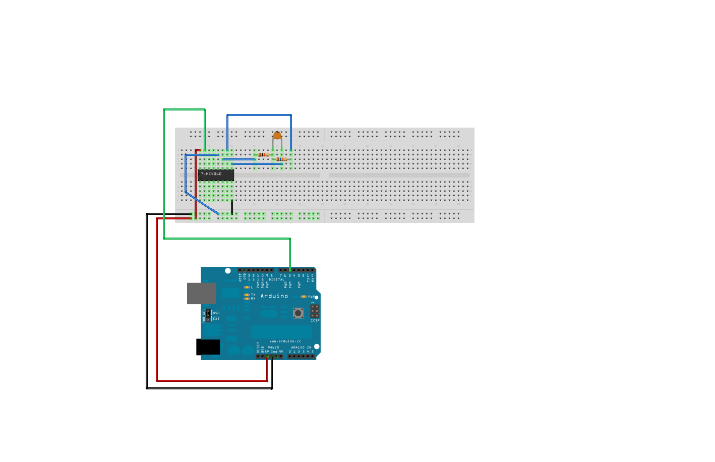
As we can see, this circuit is as simple, as the previous. This time charging and discharging the capacitor is handled by the IC. The frequency is dependent on RC circuit attached to it and impulse width can be calculated with the following equation:
t = 2,5 * R1 * C
Is it true that it reminds us something?
As we know from physics, frequency is calculated by inverting the time:
f = 1/t
In our application, base frequency is:
f = 1 / (2,5 * 16 * 10^3 Ω * 330 * 10^-12) = 1 / (13200 * 10^-9) = 0,000075758 * 10^9 = 75758 Hz
I’ve mentioned, that 74HC4060 is frequency divider. It means it has a couple of outputs with divided base frequency. These pins are:
- 7 – frequency / 16
- 5 – frequency / 32
- 4 – frequency / 64
- 6 – frequency / 128
- 14 – frequency / 256
- 13 – frequency / 512
- 15 – frequency / 1024
- 1 – frequency / 4096
- 2 – frequency / 8192
- 3 – frequency / 16384
I used pin 15, so the frequency is divided by 1024. This will give us about:
75758 / 1024 = 74 Hz
Of course, another divider can be choosen. The smaller divider, the higher accuracy.
In such a circuit, the frequency can be read with “FreqCounter” library.
unsigned long get_humidity()
{
  FreqCounter::f_comp= 8;
  FreqCounter::start(100);
  while (FreqCounter::f_ready == 0);
  long int freq = FreqCounter::f_freq;
  unsigned long humidity = map(freq, HUMIDITY_0, HUMIDITY_100, 0, 100);
  if (CALIBRATION == 1)
    return freq;
  else
    return humidity;
}
The callibration is done like in the previous case, by writing down values for peripheral values and scaling them to normal values using “map” function.
This time any additional changes in program code shouldn’t turn the callibration out.
For antiques lovers
I found in wardrobe a old IC – UCY 7404 in TTL technology, manufactured by non-existing today Polish company – CEMI. It also can be used to make a generator.
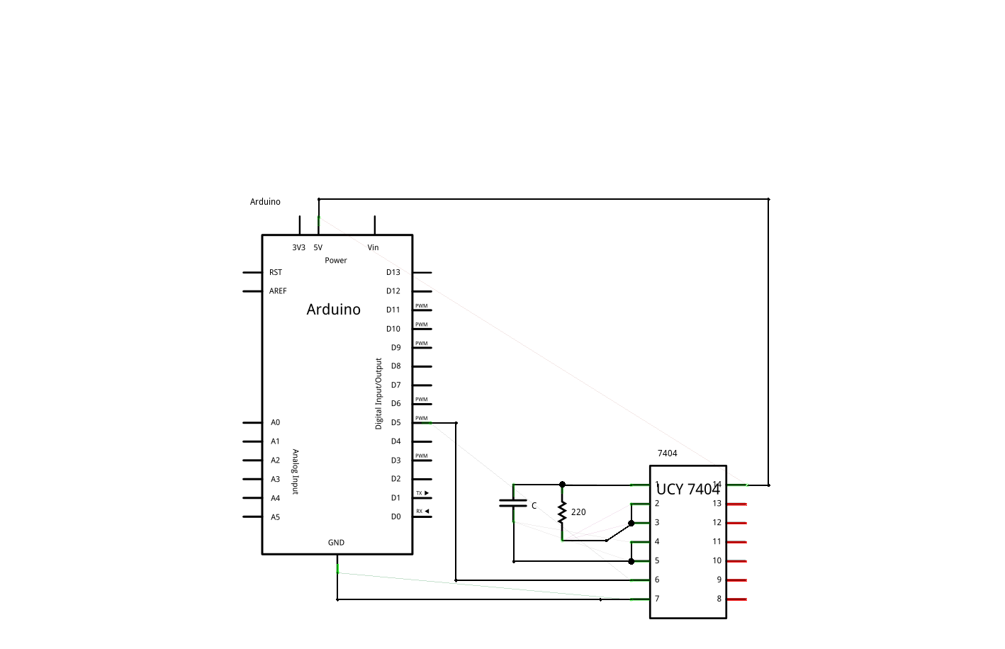
Frequency is calculated, as previously, with this equation:
t = 3RC
f = 1/t
I used 330 Ω resistor.
We are using the same program, paying attention to far higher frequency.
Source codes:
– Analog humidity measurement
– Humidity measuring with frequency
References:
– Capacitance measuring – Arduino Wiki
– Humidity and temperature measuring station project
– Description of 555 timer – Wikipedia
– Układ RC Wikipedia (PL)
– Examples of using 74HC4060
– SI units prefixes
– Dew point – Wikipedia
– Capacitor – Wikipedia
– Frequency measuring with Arduino
hai. im about to use your code on this link
https://starter-kit.nettigo.eu/2010/humidity-sensor/#more-161
when i uploaded it in arduino uno. it said ‘FreqCounter has not been declared’ . why ?
please reply this
Thank you so much for this code, it really helped me get through this project