Indicator – how to use a button
Weekend month ago became rainy, so I decided to stay at home with my three children. It was a kind of challenge to survive it without strained nerves :)
My son (3 years and a half) is on the stage of racking the carpet in every way with every toy car and train available, so I came up with idea of dicator, as he called it…
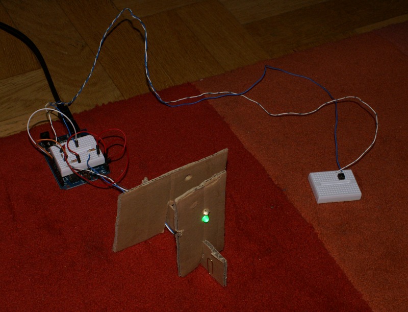
Thirty minutes and I succeded to make such a thing. I hoped it would arouse interest for the next half an hour, but it turned out to be essential component of obstacle courses builded on the carpet for a couple of days.
How it works?
The literature first – the idea was to make a simple indicator changing its state after pressing a button.
The red LED diode we connect to digital input number 3, the green to no. 3 and the button to no. 4 input.
Circuit diagram:
Code:
int buttonPin = 4;

int LED = HIGH;

int greenPin = 02;                // LED connected to digital pin 13
int redPin = 03;
int infraPin = 0;
int val = LOW;
int prev = LOW;

#define ST_OFF 0
#define ST_ON 1
#define ST_PULSE 2
int status = ST_OFF;

//initial configuration
void setup()
{
  pinMode(greenPin, OUTPUT);      // sets the digital pin as output
  pinMode(redPin, OUTPUT);      // sets the digital pin as output
  pinMode(buttonPin, INPUT); // sets the digital pin as input
  Serial.begin(57600);
  digitalWrite(redPin,HIGH);
  digitalWrite(greenPin,HIGH);
}

void display_status() {
  int static pulse = LOW;
  int static count = 5;
  switch (status) {
    case ST_OFF:
    off(redPin);
    on(greenPin);
    break;
    case ST_ON:
    on(redPin);
    off(greenPin);
    break;
    case ST_PULSE:
    off(redPin);
    digitalWrite(greenPin, pulse);
    pulse = !pulse;
    delay(400);
    count--;
    if (count==0) {
      status=ST_ON;
      count=5;
    }
  }
}

void next_status() {
  switch (status) {
    case ST_OFF:
    status = ST_PULSE;
    break;
    case ST_ON:
    status = ST_OFF;

    break;
    case ST_PULSE:

    break;
  }
}

void on( int pin) {
  digitalWrite(pin,HIGH);
}
void off( int pin) {
  digitalWrite(pin,LOW);
}
void loop()
{
  val = digitalRead(buttonPin);
  if (val == HIGH && prev == LOW) {
    next_status();
  }
  prev = val;
  display_status();
  delay(50);

}
The indicator can be in three states: off (ST_OFF, green light), on (ST_ON, red light) and pulse (ST_PULSE, green flashes).
In the main loop is performed a test, if the button was pressed. If yes, it goes to next state (next_status) excluding ST_PULSE, in which it stubbornly stays. Thanks to it, pressing the button during flashing don’t cause jumping to next state.
After that, the state according to current status (display_status) is displayed. Here the flashing is implemented and, after a proper number of loops, the state is changed to ST_ON, which stands for red.
display_status could be source of problems if it was more complicated circuit. It adds its own delay in ST_PULSE (delay(400)), changes state – asking for trouble. But in such a simple circuit – it can be.
What new?
The new part, which we weren’t using is a switch. Simple switch, whose pressing Arduino should detect.

Potential trap – why is there a resistor? Why don’t like this:
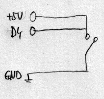
Well, when the switch is turned off, everything is all right. Digital input is connected to the supply voltage and remains in high state, but after turning the switch on, supply voltage is shorted to the ground, what may damage the supply device.
In case of not using the supply voltage, we should realize that when the button isn’t pressed, then the digital input remains not connected and it may be improperly detected by Arduino. The state of this input is random, high or low. Pulling it up to +5V with resistor makes us sure that the state will be stable and device not damaged.