Temperature and LCD
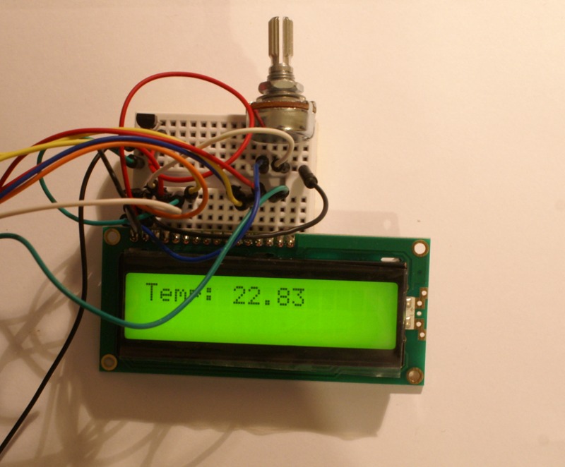
In Nettigo recently appeared LCD kit for Arduino – it is 2×16 alphanumeric LCD with soldered connector fitting to a breadboard and 10 kΩ linear potentiometer for contrast regulation.
The LCD module has HD44780-compatible controler, what means LiquidCrystal library will be able to handle it. How to connect it?
Let’s begin from the code:
#include <LiquidCrystal.h>

float temp;
LiquidCrystal lcd (12,11,10,9,8,7);

void setup() {
  analogReference(EXTERNAL);
};

void loop () {
  temp = analogRead(0)*3.3/1024.0;

  temp = temp - 0.5;
  temp = temp / 0.01;
  delay(500);
  lcd.print("Temp: ");
  lcd.print(temp);
  lcd.print("        ");
  lcd.setCursor(0,0);
};
Basic LCD handling boils down to connecting (I’ll tell about it later) and initializing it:
LiquidCrystal lcd (12,11,10,9,8,7);
The code above defines lcd variable, which will be used for communicating with the module. We will assume the simplest form here, so we are wiring it up:
- RS pin of the module
- ENABLE pin of the module
- Data pins of the module: D4, D5, D6, D7
In this example 12 – RS, 11 – ENABLE, 10-7 D4-D7. Apart from this we need to connect R/W signal to ground (we won’t write anything to it) and power. Even if we’ve connected it all, the display shows 32 little black squares. We need also to set the contrast, providing voltage in range 0 – 5V to Vo pin of the LCD. To be able to adjust it, we will use a potentiometer included in the kit. Everything illustrated in Fritzing (the transistor works as MCP9700, because there isn’t such a part in Fritzing, package is the same – TO-92):
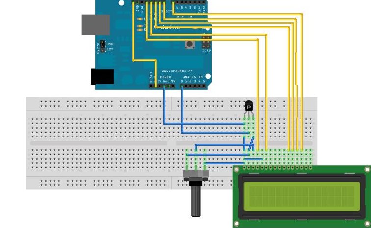
After that, in loop we are reading temperature form MCP-9700 (described in this post). Having the temperature already, we are showing Temp: text and the reading, and going back to the beginning.
How to improve the temperature measurement?
Temperature reading (in form of voltage measured by analog input 0) is given by MCP9700 with accuracy dependent on voltage converter in Arduino. It’s 10-bit and measures voltage from 0 to 5V by default. 10 bits mean that we have 1024 steps in voltage reading. Thus, the voltage is measured with 4.88 mV (5/1024) resolution.
MCP9700 sensor has 10 mV / degree resolution, so it virtually means that we have 0.5 degree accuracy (it’s not about sensor’s quality, it’s about how Arduino measures the voltage).
Arduino’s A/D converter is able to be provided with external reference voltage (AREF – the peripheral pin in the digital outputs row), which replaces 5V. This voltage can be higher or lower than 5V EDIT: Unfortunately, I made a mistake here – converter’s datasheet tell that maximum reference value is the supply voltage – for Arduino it means 5V. If someone needs to measure higher voltage, then voltage divider always could be used…
WARNING!
Potential risk. According to the reference of analogReference function, the default setting (when analogReference isn’t invoked at all or invoked with DEFAULT value) could damage the microcontroller on Arduino board when using external AREF!
MCP9700 datasheet shows that maximum output voltage is 500 mV+ 125*10mV = 1.75V. It would be best to force the converter to measure voltage in range 0-1.75V, but it requires to add a voltage divider. This is not difficult, but in order not to complicate, we will use a simple measurement quality improving method, without any additional elements. We will exploit the fact that Arduino provides a 3.3V voltage, apart form 5V and we can improve measurement resolution without any problems.
Because of this in setup the analogReference(EXTERNAL) (it’s not enough to supply a voltage to AREF) function is invoked and in loop the tempreature calculating formula is changed. After changing the reference voltage we have 3.2 mV step, which means the temperature is measured with 0.3°C accuracy and not 0.5°C, like before.
NOTE – the improvement affects only the reading, not the measurement itself. The sensor still has +-2°C accuracy :) . This thick will improve only our mood, because the reading doesn’t jump so much :)
Of course, change of AREF affects all of the analog inputs…
One thought on “Temperature and LCD”