When it lacks of current
Sooner or later in experiments with Arduino we will want to drive some kind of device, which needs more than 40 mA to work (40 mA is limitary value, because it’s maximum current that Arduino digital output can supply) It may be a relay, lighting bulb or other current-greedy device.
What to do?
We can use a transistor as an amplifier. Analog techniques is very broad issue, which I don’t know very much (everyone who has studied with me know what I mean :) ), but here I will attempt to present a few informations about driving devices with higher current demand. This example is based on materials from Arduino Starter Kit available on Nettigo.eu.
What you have to know about transistors.
Types – regarding of structure. Basic types are bipolar and field-effect (unipolar). We will focus on the bipolar. They have two groups: NPN and PNP. The difference in structure is other arrangement of semiconductor. Difference in using them is other way the current flows in the transistor, so there are two configurations of the supply voltage.
It seems easier to use NPN transistors with Arduino, because they need to be polarised with positive voltage that Arduino provides on digital output.

Bipolar transistors can work in many applications and each of them can be used in other way. We need to switch high current with low current from Arduino output. To precise, the application we will use is called transistor switch. In this application the transistor is switched between two states: saturation and cutoff.
- cutoff: UBE is too low to bias the base-emiter junction. Thus, no current flows through the collector.
- saturation: such a large current flows into the base, that the law IC=hFE*IB isn’t true anymore. In this case, UCE voltage hardly reach zero.
Virtually, the collector current is limited only by the load – what’s connected between the collector and the ground. Current efficiency of our power supply also is a limitation. You must also be careful to not exceed the maximum allowed collector current, which, for currently supplied with Starter Kit MPS2222A transistor equals 600mA.
How it looks in practice?
If we supply a 1 mA current to base, the maximal collector current will be 35 mA (1mA * 35). In case of 10 mA – IC will be max. 350 mA. If IB equals 20 mA, IC will be max…. 600 mA. 600, not 700, because 600 mA is maximum collector current of MPS2222A.
It is worst case, because hFE may vary for different copy of transistor, for one can equal 35, for another 40 – then maximum transistor current 600 mA will be achieved already for 15 mA IB.
Before sketching the circuit – rules of polarising NPN transistor to work as switch:
- emitter connected to ground
- positive voltage on base (switch is on) or 0 (switch is off)
- collector connected to supply voltage through load
So:
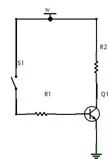
When we close S1 switch (it equals setting Arduino digital output in high state) UCB will be 0.6V, a current starts to flow into the base. It must be high enough to saturate the transistor, so UCE must fall below UCE(sat) (collector-emiter junction saturation voltage). According to the datasheet UCE(sat) value depends on IC and IB currents. We can estimate it as about 0.3V.
In Arduino Starter Kit there isn’t any part, which could receive current higher than 40 mA, but we can join parallelly some LEDs to demonstrate this issue in practice.

Let’s estimate current flowing through one diode – voltage drop between collector and emitter in saturation state is 0V, voltage drop on red diode – about 1.8V so on the resistor – 5-1.8 = 3.2. For resistors R2-R5 of value 280 Ohm the current flowing through them should be 3.2/280 = 11.42 mA. For 4 diodes it should give about 45 mA.
Before connecting the transistor we should know which terminal is which:
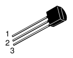
- emitter
- base
- collector
Physically connections illustrated in Fritzing (frankly admitting – this time it won’t be easy to read. The images probably will be better illustration):
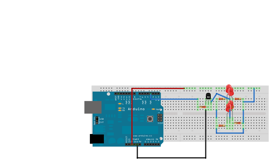
And two photos (on the left of breadboard there is other circuit assembled, so everything what is visible under 25th row doesn’t matter):
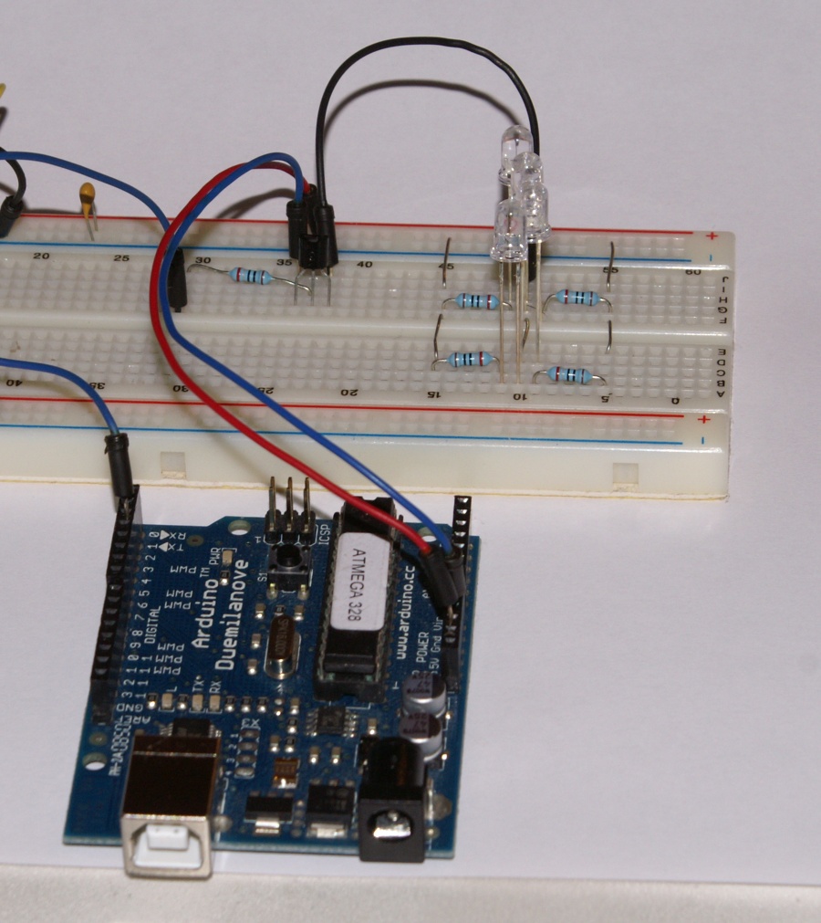
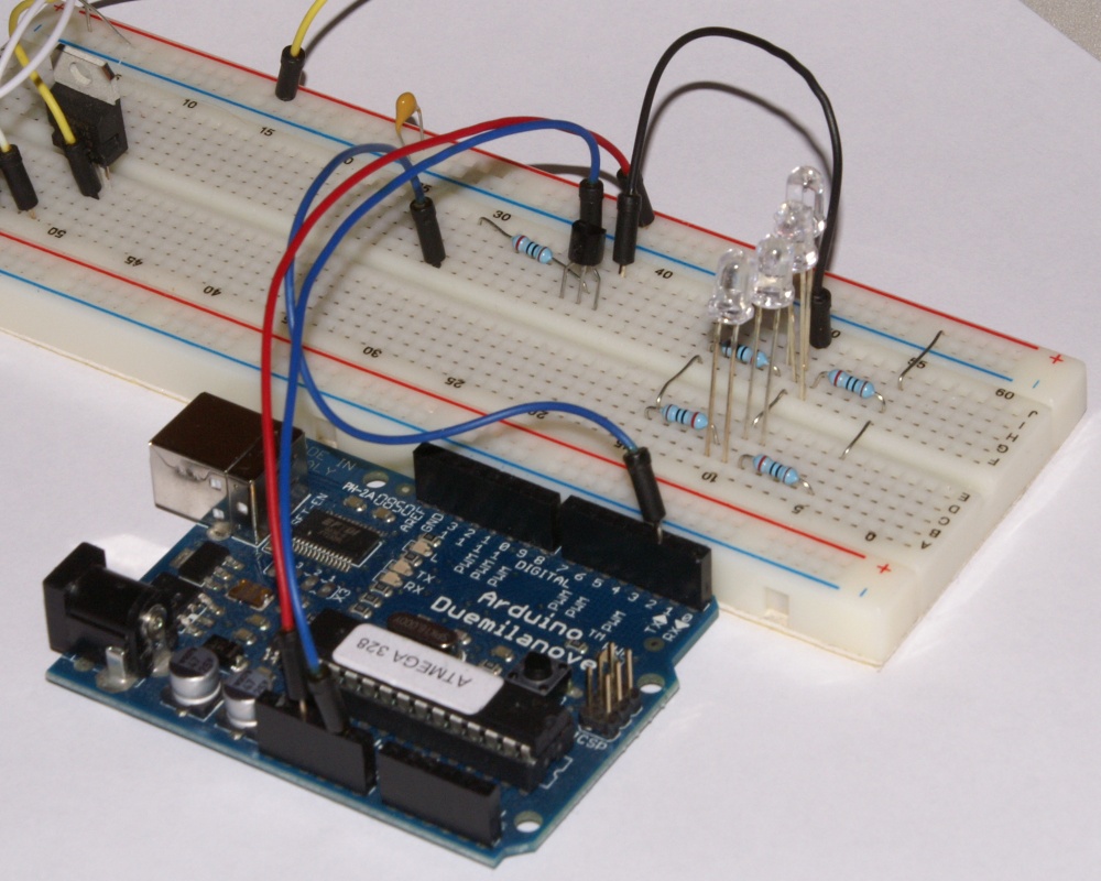
Assembly warning – cutted off resistor terminals are perfectly suitable for making short jumpers on breadboard – they are clearly visible in the picture.
Bill of materials generated from Fritzing (all the required parts are included in Arduino Starter Kit from Nettigo):
Fritzing Bill of Materials

Sketch: 	tranzistor.fz
Date: 	Mon Dec 14 10:30:33 2009

Arduino       Arduino Diecimila
Breadboard1   Generic Breadboard
LED1          Red LED - 5mm
LED2          Red LED - 5mm
LED3          Red LED - 5mm
LED4          Red LED - 5mm
Q1            NPN-Transistor
R1            220Ω Resistor
R2            220Ω Resistor
R3            220Ω Resistor
R4            220Ω Resistor
R5            220Ω Resistor

Shopping List

Quantity	Part

5		220Ω Resistor
1		Arduino Diecimila
1		Generic Bajillion Hole Breadboard
1		NPN-Transistor
4		Red LED
Of course, 220Ω resistors are the ones supplied with Arduino Starter Kit for LED diodes and may have other values – from 200Ω to 280Ω. Regardless of the values, this circuit will work.
Sketch for Arduino is classical example of Blink:
/*
 * Blink
 *
 * The basic Arduino example.  Turns on an LED on for one second,
 * then off for one second, and so on...  We use pin 13 because,
 * depending on your Arduino board, it has either a built-in LED
 * or a built-in resistor so that you need only an LED.
 *
 * http://www.arduino.cc/en/Tutorial/Blink
 */

int ledPin = 02;                // LED connected to digital pin 13

void setup()                    // run once, when the sketch starts
{
  pinMode(ledPin, OUTPUT);      // sets the digital pin as output
}

void loop()                     // run over and over again
{
  digitalWrite(ledPin, HIGH);   // sets the LED on
  delay(4000);                  // waits for a second
  digitalWrite(ledPin, LOW);    // sets the LED off
  delay(2000);                  // waits for a second
}
At the end, the values measured in real circuit, for 280Ω resistors:
- supply voltage – 4.96 V
- UCE voltage – 0.03 V
- voltage drop on lighted LEDs – from 1.86 to 1.93 V
- current flowing through LEDs (without incorporating real resistance R2-R5, each of them has 5% tolerance) – from 10.7 mA to 10.9 mA
As homework – it is possible to change pin used to drive transistor to any supporting PWM and control brightness of the diodes using analogWrite instead of digitalWrite. Movie illustrating such a modification:
Driving over 40mA of current – PWM version from Starter Kit on Vimeo.
Today I wrote slightly long article, but I had to include some theory here. I tried hard to avoid inaccuracies, but analog techniques aren’t my strong point :) If you notice any errors, please let me know, I will try to correct them.