Change GPIO used by ESP01 relay module
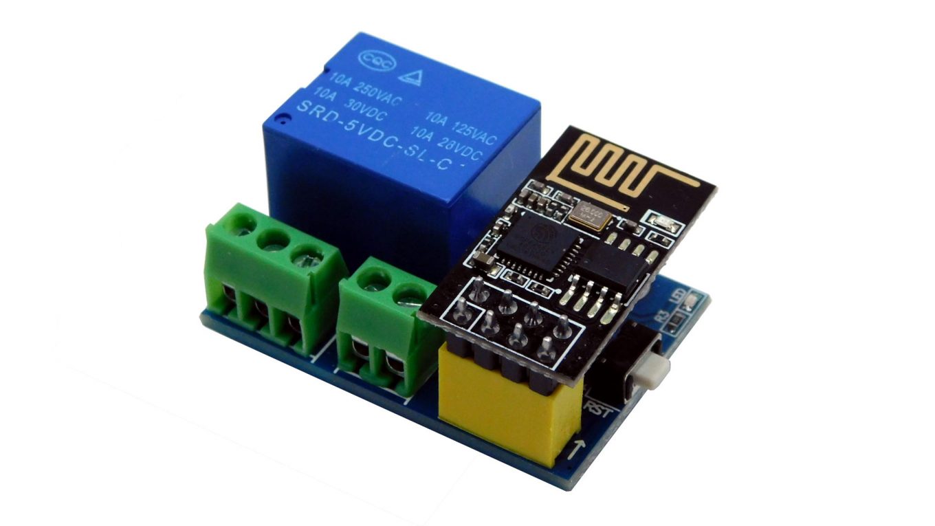
Today we have added new ESP related module to Nettigo offer. It is small relay module for ESP01. Small size, one relay and ESP01 connector is good place to start with controlling devices via WiFi. Using this module is quite straightforward, however this time I’ll write about one potential issue with it.
Designer decided to use GPIO0 as relay control pin. The problem is when ESP8266 is powered up or after reset state of GPIO0 shortly changes, enabling relay for a short moment with each reset or power up. For most devices controlled thorough relay it does not matter, but sometimes it can be an issue.
ESP01 has only 4 GPIO pins available. These are:
- GPIO0
- GPIO1 – Serial TX (direction out) – so with each reset there is some communication sent by ESP8266 – not interesting for us
- GPIO2 – this IO is used in ESP01 to control LED. And it’s used on startup, so not interesting for us
- GPIO3 – this is Serial RX (incoming) and there is no state change on reset (did not get through ESP8266 specs, just an observation on ESP01s with ESPEasy on board.
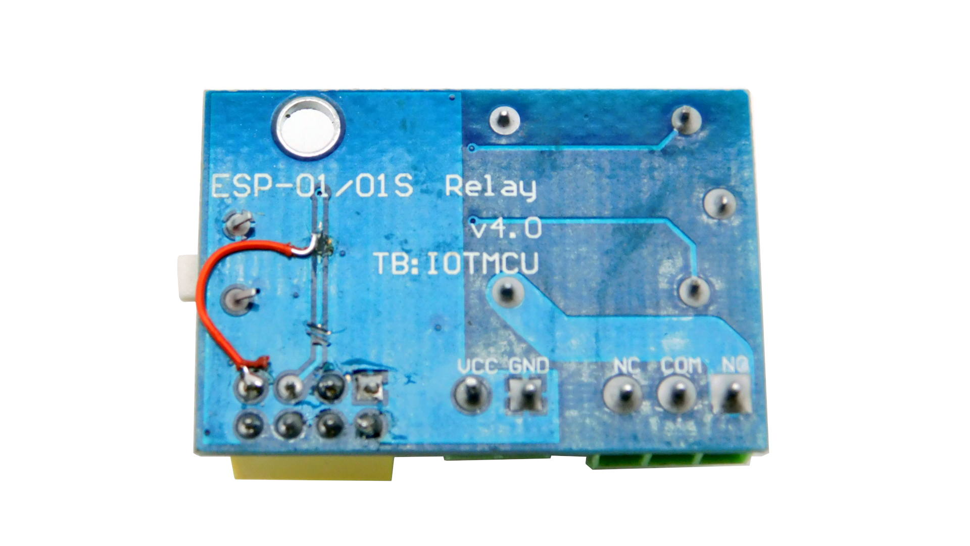
So, if You look at back of module PCB there is a small trace on the left from 10 pins of ESP01 connector leading to upper edge of PCB. That is control signal.
You will need a sharp knife (utility knife) solder iron and hookup wire. Cut trace near of ESP01 connector and somewhere in upper part scratch soldermask.
Warning – trace is narrow, pay attention not to scratch soldermask on copper plate region (GND). You can do scratch on end of trace, where is via on other side of board. Trace there is a bit wider.
Then solder hookup wire to scratched trace and to the GPIO3 pin. Looking from bootom side of PCB it is one in upper left corner of connector.
And that’s it – now relay is controlled by changing GPIO3 to low level.
Thanks for your article. Using this module the ESP-01 with relay, I first connected it to a FTDI serial adapter.. (Had to connect GPIO0 to ground on startup to get into the download mode). Downloaded
Tasmota Basic to it. Connected to network, ID’d it.
Biggest issue was Module Configuration. First I chose “Basic”. It didn’t have gpio0 as a choice. I changed it to “Generic” and the GPIO0 was available. I set it up as a relay. Worked without soldering.
Important, I first supplied 3.3 volt to module, Relay did not work. At 5 volts DC, all is working.
Hope this helps.
Rick S.
Regarding relay – I have not seen relay rated for 5V which could work at 3.3V. Most of them needed 3.8V and more…