
Arduino and LED display – matrix driven by MAX7219
MAX7219 is chip to drive 7seg LED displays. Not just one, but 8 of them.
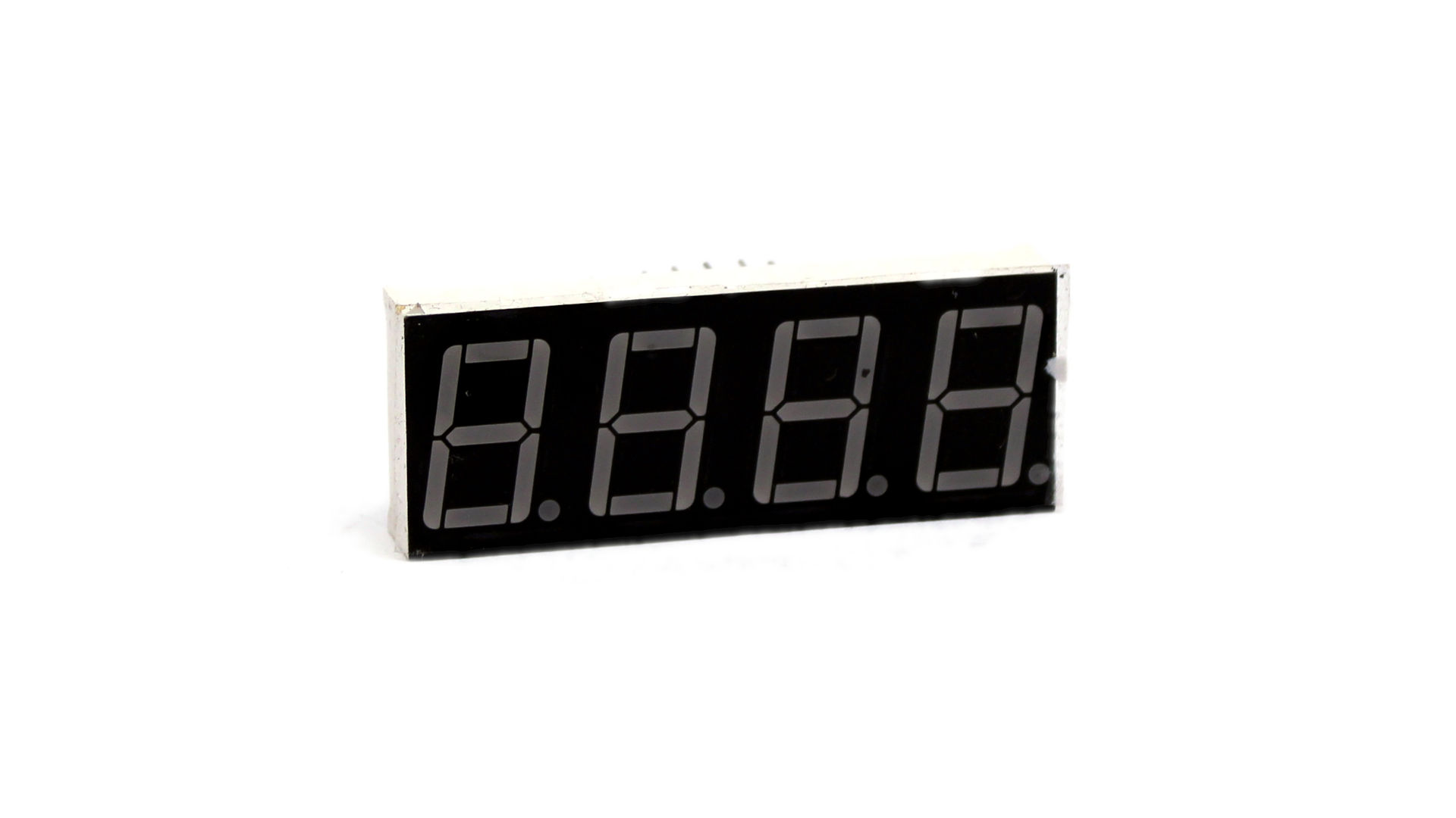
7 seg – but 8 LEDs – there is also a dot. So, each digit is built from 8 LEDs and each MAX7219 can drive 8 digits – we can built 8×8 matrix driven by single MAX. Get few such modules and we have text display!
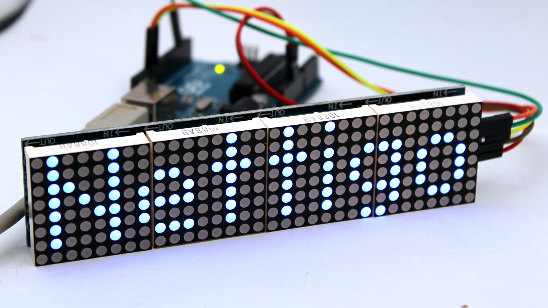
What You need to build such? First – MOD-1671 8×8 LED matrix 8×8 driven MAX7219, Arduino UNO and some jumper wires (F-M in this case).
MAX7219 uses SPI as interface, so connecting is easy:
- GND -> GND
- 5V -> Vcc
- D11 (MOSI) -> DIN
- D3 -> CS You can use other pin, Chip Select can be any pin
- D13 (CLK) -> CLK
Communication with MAX7219 is one directional, so only MOSI need to be connected. MISO is not even brought out.
So, device is connected now we need some software to control it. We will use two libraries. First one (MD_MAX72XX) does basic communication stuff with MAX7219 and second (MD_Parola) deals with more useful (for us) concepts like animations, effects and multiple display zones… Both are written by the same author and are maintained for many years – so we can hope it will be true also in future.
I will skip library installation in Arduino IDE. Even with IDE 2.0 which seems like a big improvement for more heavy users – I still don’t use them. For many years I use Platformio for all my projects (with CLion, which I prefer over VSCode). Very important feature of Platformio is platformio.ini file with its capability to select libraries and freeze version used in given project. With other platforms it is common to share libraries between projects (so it can lead to version conflicts). Or when getting back to project after a few years it turns out that newest library version has different interface and project does not compile.
Ok, back to our example here is a code to download or browse it directly on Github.
When using MD_MAX72XX most important is to select proper hw type. There are many modules on market with different types of connection. For our module You should use MD_MAX72XX::ICSTATION_HW. With other types You will get letters rotated or in wrong order. If You have some other, custom module here You can read how to customize library for Your hardware.
In Your sketch You need create MD_Parola object:
MD_Parola mx = MD_Parola(HARDWARE_TYPE, CS_PIN, MAX_DEVICES);
HARDWARE_TYPE – as I wrote. CS_PIN has to match to pin used as Chip Select. MAX_DEVICES – number of MAX7219 chips in chain. This is not number of whole modules (MOD-1671) just chips. Each MOD-1671 has 4 MAX7219 (4 x 8 = 32). If You connect more MOD-1671 in chain then MAX_DEVICES should be equal to total number of MAX7219 in chain. For single module MOD-1671 it is 4.
So, we can test some effects. First mx.setTextAlignment declares how text should be aligned on display (left, right, center). Display brightnes can be controlled via mx.setIntensity (in 0 – 15 range). If You need some basic animations check mx.displayText. Function takes 6 arguments: text, alignment, speed of animation, how long it should be displayed as static text and in and out animation effect. For example: mx.displayText(“Abc”, PA_CENTER, 300, 0, PA_SCROLL_LEFT, PA_SCROLL_RIGHT). Check this example added to library. You can also browse more examples there.
MAX7219 and ESP8266
In MAX7219 data sheet You can find info, that high logic level has 3.5V as minimal value. I’ve seen projects where ESP8266 directly drives SPI interface of MAX7219, however it is out of spec (high logic level in ESP8266 is 3.3V). So if You use ESP8266 (or other µc running at 3.3V) and You experience some oddly behavior then first connect ESP to MAX via logic level converter. That way You will be sure problem is not caused by too low voltage on SPI bus.