Shifted LEDs
The last piece of Arduino Starter Kit, which still remains undescribed is small, but powerful integrated circuit – shift register. It is 74HC595, SIPO type (Serial-In, Parallel-Out) shift register with 8 parallel outputs.
Shift register has serial input and some (usually 8) parallel outputs. What it means? With every clock impulse the output states are shifted by one position. So, logic level of the 1st output appears on the 2nd one. Content of the 1st output is changed depending on serial input content.
How can we take advantage of this?
We should consider using shift register in every place which needs many logic outputs. You can say that three pins can control many more outputs. Let’s see it on the simplest example – LED diodes.
This article is based on tutorial published on Arduino.cc, which is source of illustrations. These are depicting more than one breadboard, but I decided to use them to speed up writing this article – making a clear illustration in Fritzing is rather impossible.
Let’s begin from wiring it up:

Power is spreaded by rails on the breadboard. On the left board the LEDs are connected with resistors. On the right one is connected the 74HC595 itself.
Its pinout:
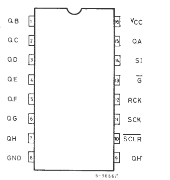
On the preceding diagram is shoved the pinout according to datasheet from manufacturer (ST Microelectronics), whose chips are in offer of Nettigo and are part of Starter Kit. On the Arduino site there is description suitable to ICs marked according to Philips nomenclature. What it means? Fortunately the only difference is signals naming (for example, outputs – in STM: QA to QH, in Philips version: Q0 to Q7), placing and functions of pins is the same. In this tutorial I will be using naming compliant with STM.
The simplest connection between Arduino and shift register looks like the following:
- +5V power to register pin 16
- Ground to register pin 8
If we don’t mind the fact that after turning the power on the LEDs may light in random configuration and we want to use less digital outputs, we can connect it like this:
- G – register pin 13 to ground
- SCLR – register pin 10 to ground
The minimal configuration to control a shift register from Arduino is (all Arduino pins are digital inputs):
- SI – register pin 14 to Arduino pin 11
- SCK – register pin 11 to Arduino pin 12
- RCK – register pin 12 to Arduino pin 8
Between RCK pin and ground there should be capacitor (1 μF – not supplied with Starter Kit). A number of experiments I made prove that it isn’t necessary :)
Here is logic diagram of the connection:

What remains? The code:
//**************************************************************//
//  Name    : shiftOutCode, One By One                          //
//  Author  : Carlyn Maw, Tom Igoe                           //
//  Date    : 25 Oct, 2006                                      //
//  Version : 1.0                                               //
//  Notes   : Code for using a 74HC595 Shift Register           //
//          : to count from 0 to 255                            //
//****************************************************************

//Pin connected to ST_CP of 74HC595
int latchPin = 8;
//Pin connected to SH_CP of 74HC595
int clockPin = 12;
////Pin connected to DS of 74HC595
int dataPin = 11;

//holder for infromation you're going to pass to shifting function
byte data = 0;

void setup() {
  //set pins to output because they are addressed in the main loop
  pinMode(latchPin, OUTPUT);
  pinMode(clockPin, OUTPUT);
  pinMode(dataPin, OUTPUT);

}

void loop() {

  //function that blinks all the LEDs
  //gets passed the number of blinks and the pause time
  blinkAll(1,500);

 // light each pin one by one using a function A
  for (int j = 0; j < 8; j++) {
    lightShiftPinA(j);
    delay(1000);
  }

  blinkAll(2,500);

 // light each pin one by one using a function A
  for (int j = 0; j < 8; j++) {
    lightShiftPinB(j);
    delay(1000);
  }

}

//This function uses bitwise math to move the pins up
void lightShiftPinA(int p) {
  //defines a local variable
  int pin;

  //this is line uses a bitwise operator
  //shifting a bit left using << is the same
  //as multiplying the decimal number by two.
  pin = 1<< p;

  //ground latchPin and hold low for as long as you are transmitting
  digitalWrite(latchPin, LOW);
  //move 'em out
  shiftOut(dataPin, clockPin, MSBFIRST, pin);
  //return the latch pin high to signal chip that it
  //no longer needs to listen for information
  digitalWrite(latchPin, HIGH);

}

//This function uses that fact that each bit in a byte
//is 2 times greater than the one before it to
//shift the bits higher
void lightShiftPinB(int p) {
  //defines a local variable
  int pin;

  //start with the pin = 1 so that if 0 is passed to this
  //function pin 0 will light.
  pin = 1;

  for (int x = 0; x < p; x++) {
    pin = pin * 2;
  }

  //ground latchPin and hold low for as long as you are transmitting
  digitalWrite(latchPin, LOW);
  //move 'em out
  shiftOut(dataPin, clockPin, MSBFIRST, pin);
  //return the latch pin high to signal chip that it
  //no longer needs to listen for information
  digitalWrite(latchPin, HIGH);

}

//blinks the whole register based on the number of times you want to
//blink "n" and the pause between them "d"
//starts with a moment of darkness to make sure the first blink
//has its full visual effect.
void blinkAll(int n, int d) {
  digitalWrite(latchPin, LOW);
  shiftOut(dataPin, clockPin, MSBFIRST, 0);
  digitalWrite(latchPin, HIGH);
  delay(200);
  for (int x = 0; x < n; x++) {
    digitalWrite(latchPin, LOW);
    shiftOut(dataPin, clockPin, MSBFIRST, 255);
    digitalWrite(latchPin, HIGH);
    delay(d);
    digitalWrite(latchPin, LOW);
    shiftOut(dataPin, clockPin, MSBFIRST, 0);
    digitalWrite(latchPin, HIGH);
    delay(d);
  }
}
This will light all the diodes, then light every diode one by one, flash all the LEDs twice and light again using another method.
The most important informations:
- shiftOut is a function from Arduino library, serially sending selected byte to specified output
- we can send data to the register by setting RCK (connected to Arduino pin 8) in low state
One thought on “Shifted LEDs”