Supla GUI Generic – smart relays without programming
If you ever wanted to implement some smart solutions in your home but you don’t know/don’t want to write you own programs to handle it there is perfect solution for you. It’s called Supla and it’s open source so anyone can use and modify it on their own. Moreover it has great community that not only helps other less advanced users on their forum but also develop new functionalities and useful tools. One of these is GUI Generic – tool that generates ready to use programs that we can flash into popular ESP8266 module and configure it by just clicking some buttons in config webpage. Then we can use it for example as light switch, temperature sensor and many more.
What will you need?
I will suggest you to use NodeMCU v2 module. It has on-board programmer and fits well on standard breadboard so you can easily prototype your final devices with it. It all depends on your needs. If your final device should be small and don’t need to have many inputs/outputs ESP8266-01 module should fit your needs. Note that in this case you will need separate programmer to flash binary files into it. If you are advanced enough you can use basic ESP8266 module, but remember about proper circuit.
Let’s start
Generating program
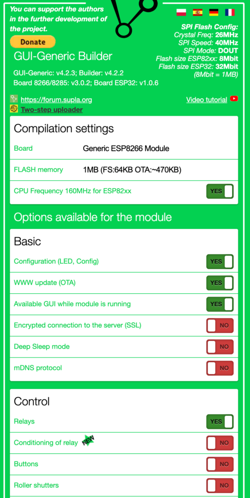
Go to https://gui-generic-builder.supla.io/ and generate binary file with almost all the default settings. Just change “Relays” option to “ON”.
Flash it
Next you will need to connect ESP8266 board to the computer and upload .bin file that you just generated. There are many tools to do it but I prefer esptool. Its easy to use console tool. Just follow instuctions on their github page to install it.
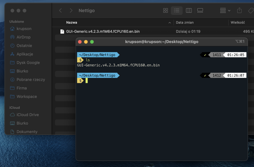
Next you will need to locate your binary file and open terminal in this location (or move there with “cd” command).
Then we will erase currently flashed ROM to ensure that we will perform clean install. Make sure you have only one ESP device connected to your computer at a time – we don’t have to specify COM port thanks to this.
python3 -m esptool erase_flash
You should see output similar to this:
esptool.py v3.1
Found 2 serial ports
Serial port /dev/cu.usbserial-0001
Connecting….
Detecting chip type… ESP8266
Chip is ESP8266EX
Features: WiFi
Crystal is 26MHz
MAC: **
Uploading stub…
Running stub…
Stub running…
Erasing flash (this may take a while)…
Chip erase completed successfully in 6.3s
Hard resetting via RTS pin…
Next we will flash new ROM:
python3 -m esptool write_flash 0x0 GUI-Generic.v4.2.3.m1M64.fCPU160.en.bin
0x0 is address in device memory where our binary file will be flashed. Last parameter is just .bin file name.
Output:
esptool.py v3.1
Found 2 serial ports
Serial port /dev/cu.usbserial-0001
Connecting….
Detecting chip type… ESP8266
Chip is ESP8266EX
Features: WiFi
Crystal is 26MHz
MAC: **
Uploading stub…
Running stub…
Stub running…
Configuring flash size…
Flash will be erased from 0x00000000 to 0x00078fff…
Compressed 495456 bytes to 353391…
Wrote 495456 bytes (353391 compressed) at 0x00000000 in 31.3 seconds (effective 126.5 kbit/s)…
Hash of data verified.
Leaving…
Hard resetting via RTS pin…
Configuration
Ok, looks like our device is flashed. After reboot you should see new wifi network
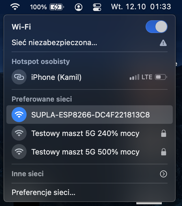
Connect to this network and open http://192.168.4.1/ in your browser. You should see GUI Generic configuration page.
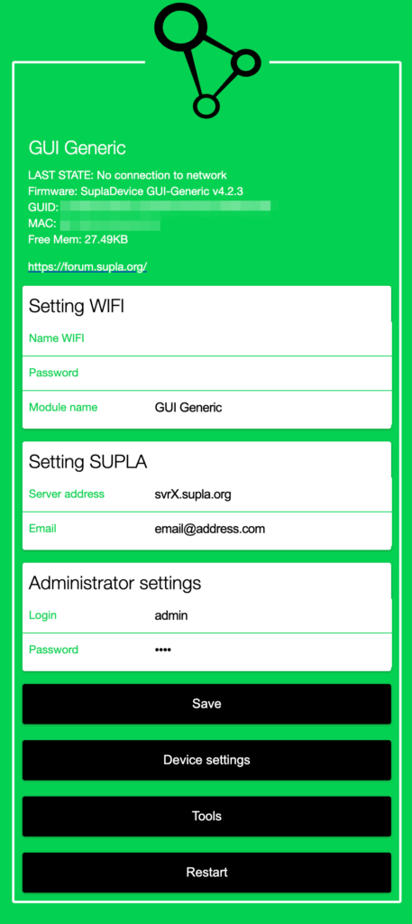
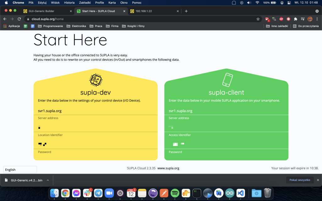
You have to enter your home WiFi credentials here and your Supla server address with login (email). You can find this in Supla Cloud dashboard.
Make sure to enable I/O devices registration in cloud dashboard before you continue.
If everything is ready you can save settings and reboot your device. After reboot you should see your device in supla cloud
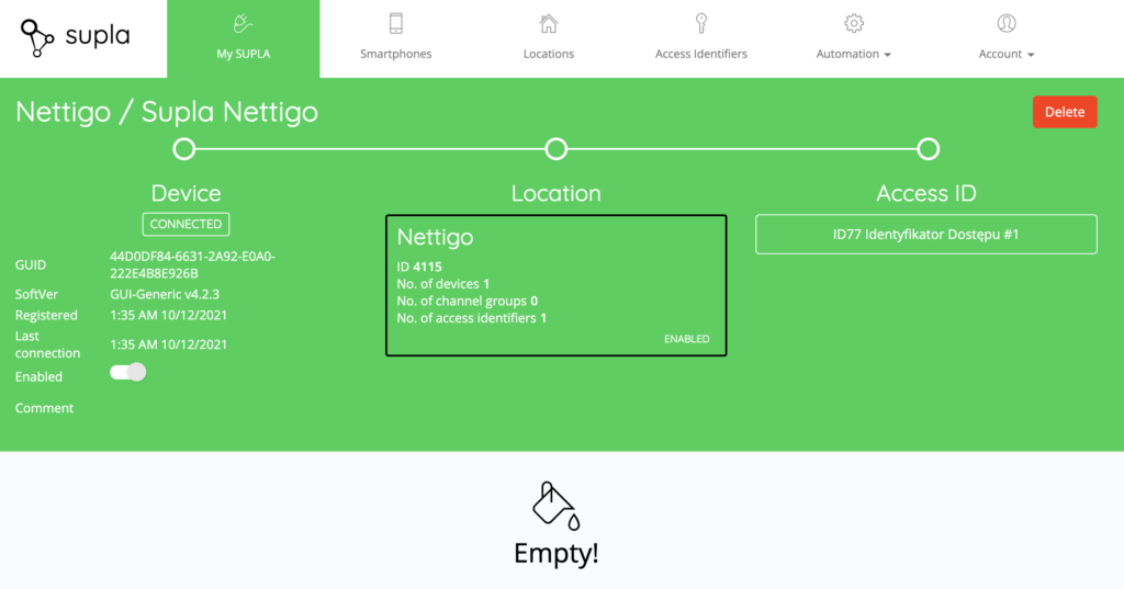
But why there are no devices? Well we have to configure them first.
Configure I/O
You need to know IP address of your ESP device in your local network. You can use nmap for this or just log in to your router and find it on DHCP list.
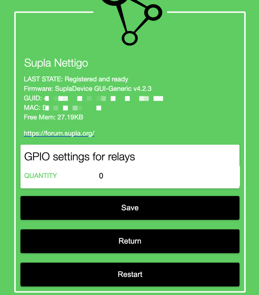
If you have IP you can enter it in your browser window and configure I/O.
Click “Device settings” button and input number of relays you want to control with Supla.
Then you will see list of relays you can configure.
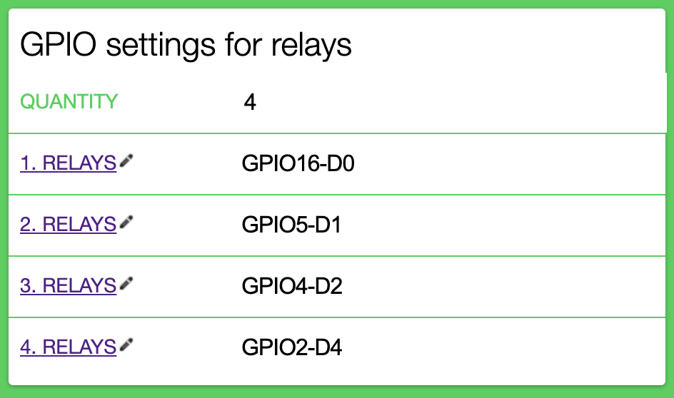
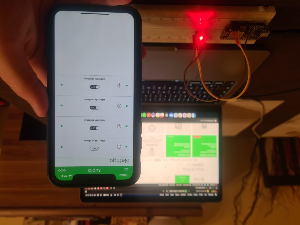
For my test case I used LEDs in place of relays. One RGB led connected to D0, D1 and D2 and on ob-board LED connected to D4. What’s important my RGB led had common cathode so every color is driven by HIGH state and the on-board LED is connected to GPIO2 (D4) with its cathode, so it’s driven by LOW state. We should set it in relay settings.
Next we can reboot the device and check Supla cloud dashboard. Now we should see 4 switches as shown below:
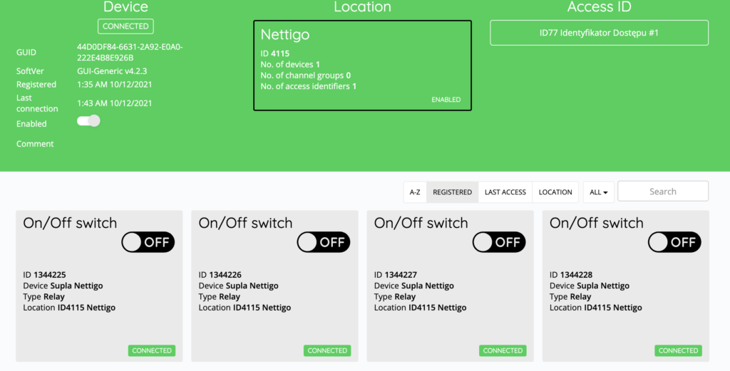
We can configure each one by clicking on it.
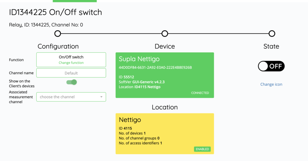
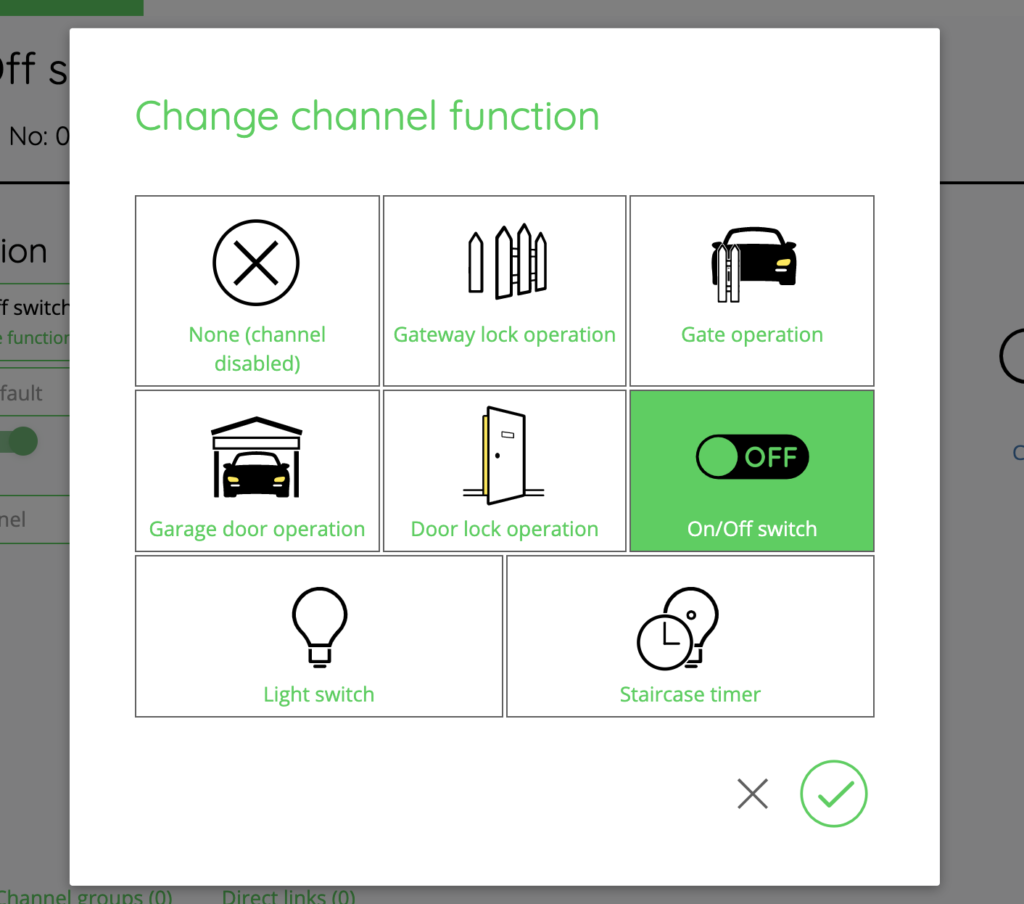
We can set a name for it or change its function for example set is as gate controller.
If we did everything correctly we can control our LEDs (relays) with Supla mobile application: